How to print & assemble the AmbiLamp
You can fit all parts on a single bed in the vertical orientation. It is recommended that you rotate the parts to have the registration holes on the build plate, and the registration pegs on top.
You will need to print:
- 1x base
- 1x cable leg intermediate
- 1x cable leg end
- 1x non-cable leg intermediate
- 1x non-cable leg end
- 1x vertical top
- 6x vertical intermediate
Optionally, you can add/remove "intermediate" parts to make the legs longer or the vertical part taller.
You will need to source an LED strip with adhesive back. I used this one.
Print settings
Recommended Print Settings
- Material: PLA
- Outer Walls: 2
- Infill: 15%
- Supports: Painted on base registration pegs and from build plate only.
This build does not see a lot of stresses (it's a lamp, after all), so it doesn't need to be very sturdy print-wise. The important part is...
Assembly Instructions
For best results: keep things as straight as possible when assembling. You can achieve this by allowing the super glue to fully dry before attempting to glue one section to another.
You will need:
- quick set CA (super) glue
- super glue activator
1. The non-cable leg
Glue the non-cable leg intermediate to the base, then, when dry glue the non-cable leg end.
2. The cable leg
To assemble the cable leg, first glue together the cable leg end and cable leg intermediate pieces together (the ones with the hole running through the middle) using the registration holes & pegs as a guide. Once dry, run LED power cable through hole of leg and through hole in base.
Next, glue the cable leg to the base using the registration marks, making sure not to get any glue on the cable.
3. The vertical pieces
It is recommended to glue two pieces of the vertical pieces to each other first so that straightness can be maintained. Ensure that the vertical top piece is on the top (it does not have registration pegs on the top of it).
Note: please pay close attention to the orientation of the vertical pieces and placement of registration holes and pegs.
4. The LED Strip
First, plug the power end of the LED strip into the power cable that was run through the base, without peeling the adhesive.
Then, peel the adhesive off the bottom (closest to the power cable) and as the adhesive backing is peeled off, press the exposed adhesive of the LED strip onto the flat side. Use scissors to trim the LED strip at the top of the lamp.
Congrats! You've got an assembled AmbiLamp ready to use!
If you'd like, let's talk about how the AmbiLamp came together.

The Story
$119.99, $84.99, "$100 off promotion"... the price of these corner accent lamps are wayyyy to high. Especially considering the cost of injection molded plastic and LEDs, the markup & margin on these things have to be in the 70% or greater region. After getting served many, many Instagram Ads, I decided that I would take matters into my own hands and design my own.
Seeing as I've recently acquired a Bambu Lab X1 Carbon, I've been itching for a project that put 3D printing at the center. I've also recently moved to the Chicago area and the new place has a lot of space that I need to do something with. I've also just been in the making mood recently as I've been starting to follow along more with the maker community (much more than I already have). It was just a perfect storm of me seeing an opportunity to make something myself that had use and was challenging.
The How
I wanted to design the full thing in CAD like I wanted it to look, and then I wanted to divide the model into sections that could be 3D printed on most 3D printers. I say "most" here because once full model was finished, I sliced into 200mm sections with the intention that they would be printed vertically. Therefore, "most" printers in this case is a printer with a >200mm Z-height printable area, or a printer with >200mm diagonal print bed (XY).
Let's move on to the pieces of this build.
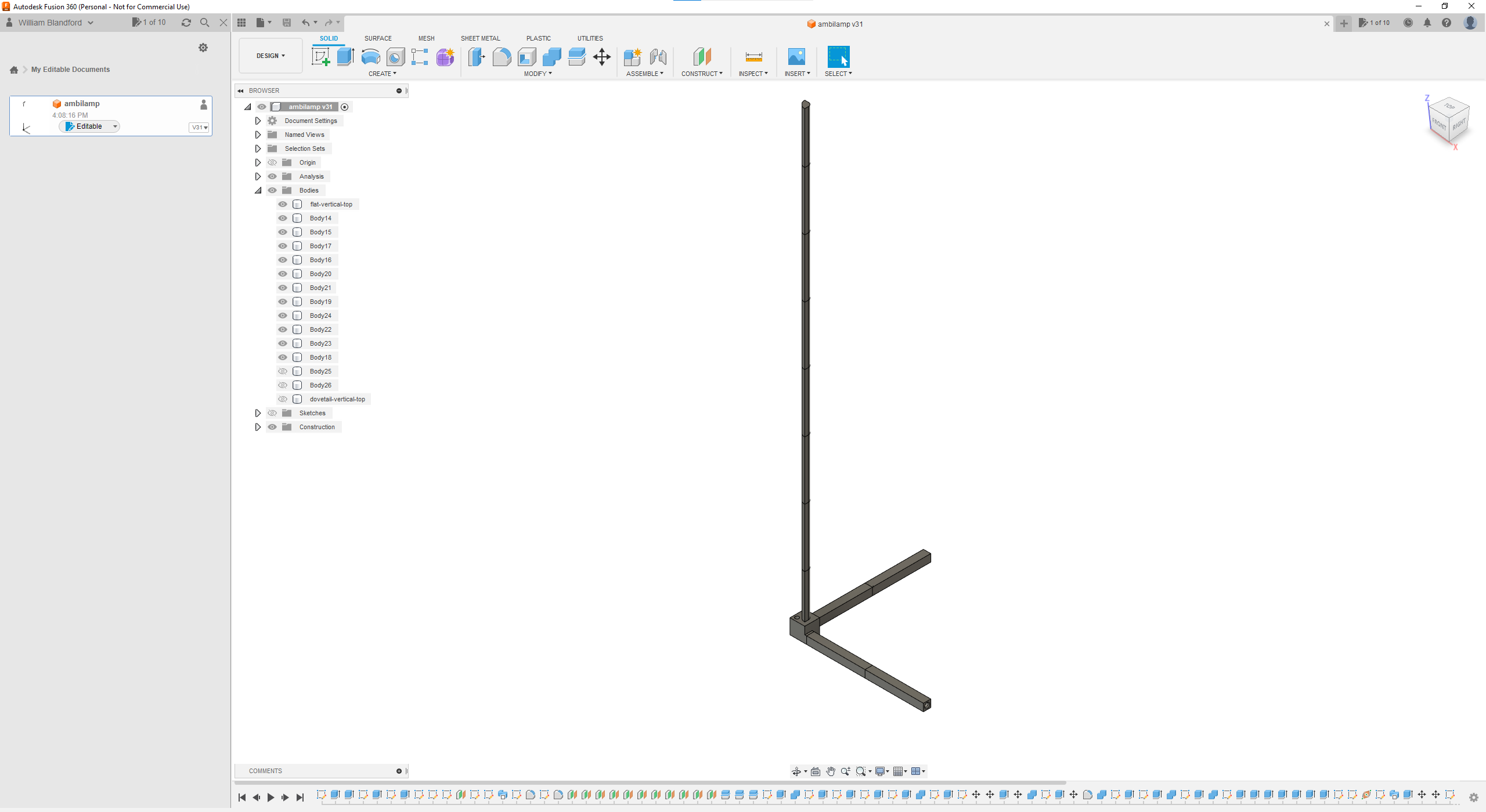
Software: Fusion360
Fusion360 is currently my CAD software of choice right now. It's simple to use, has a nice UI, it's free*, and it runs well on my machine. I say it's "free*" because you can only have up to 10 files declared as "editable" at a time, and Autodesk also requires you have a connection to their "cloud" to do specific things. It's a great piece of software in my opinion, it just kind of sucks to have to use a closed source piece of software like this. I am, though, testing out the SolidWorks Maker edition. I'm not sure it's much different between the two when it comes to features and lock-in. Maybe look for a piece on that?
And now, for the requirements...
Requirements
Just like any good engineer knows, you have to set bounds and rules to a project. Not everyone has the unlimited budget of a DoD contractor! Setting rules and bounds also helps bring fulfillment to the project, in my opinion. All engineering is cool because of the rules within which you have to work. So, here are the (relatively loose) bounds I put on this project:
- all structural parts need to be 3d printable
- it can stand on it's own
- the power cable can run through one of the legs
- the LED strip is easily attached and can easily be sourced
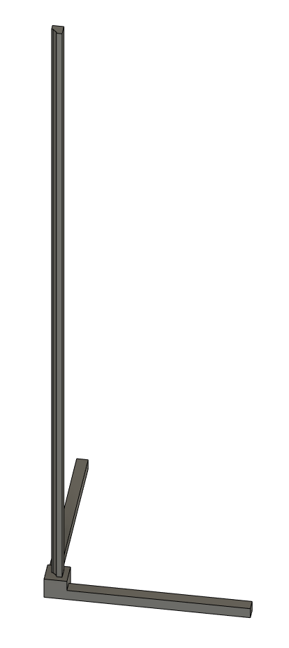
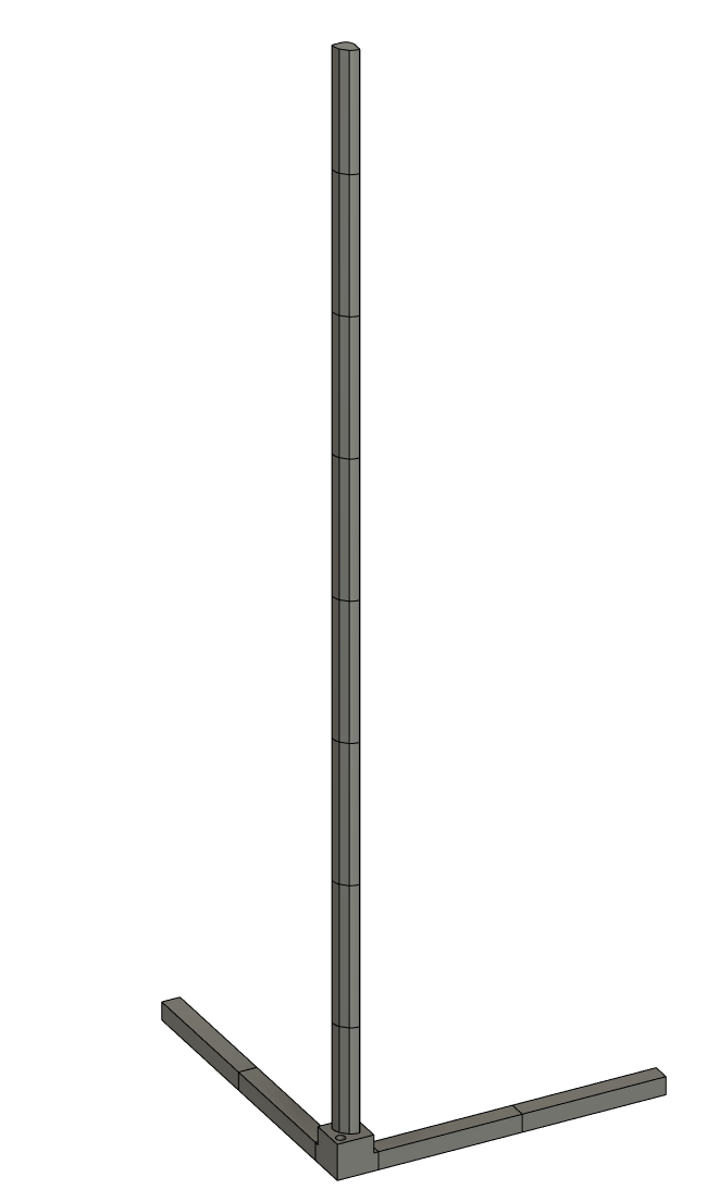
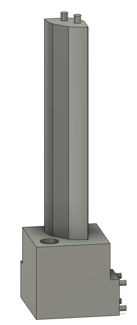
So, I started there, and ended up here:
What you're looking at here is the full model of the AmbiLamp! It's broken into 12 different parts; a cable leg with a hole down the middle (2), a non-cable leg (2), a base (1), and seven (7) vertical pieces to get it to stand 60 inches.
Let's start from the beginning...
First, the base model was sketched:
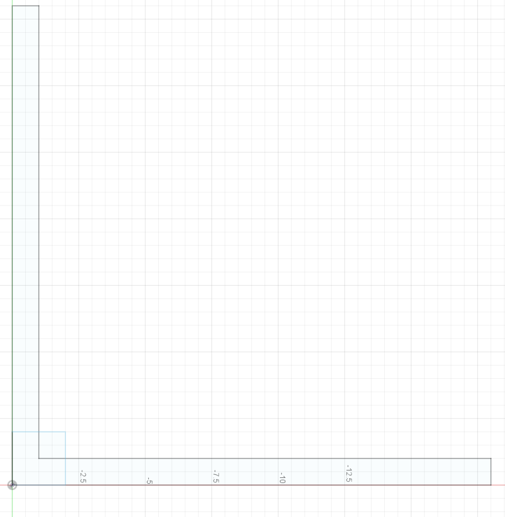
And then extruded out:
This was where version one stopped. As you can see from these images and the images below, there were a few changes to the vertical lamp post, the primary change being the filleted edges on the side of the flat edge that is for the LED strip.
Cutting it up
As I mentioned above, one of the primary requirements of this project was for this entire lamp to be 3D printable. The only way to do this is to cut the model up into sections that could fit inside a 3D printed build volume. Again, as mentioned above, I decided to cut the model up into 200mm sections with offset planes.
Here's what that looks like:
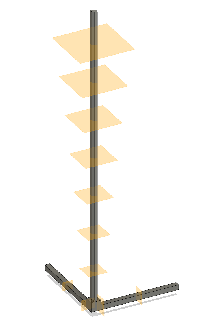
Then with the "Combine" function, but set to "cut" using the offset planes at the cutting tool and the target body as the full, uncut model you end up with:
Now that the model is all cut up, I want to explain each individual section. What I realized after cutting the model up was that the interface sections, so let's dig into how I solved for that, also!
(All About that) The Base
The base is a simple enough design. It's a 2-inch cube with two smaller 1-inch cube extrusions for legs that go out 18-inches.
As you can see, the base is designed to have a 0.5" hole from the middle through the right side. One of the large benefits of this design, since everything is designed symmetical along a 45-degree angle from the x-axis, you can mirror this part in the slicer to have the hole through the other leg!
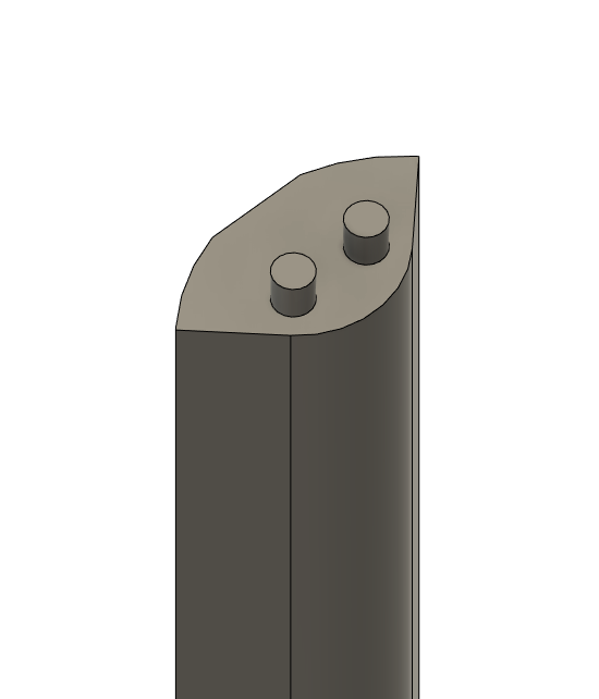
You can also point out that there are registration pins for assembly. Here's what that looks like at a cross section:
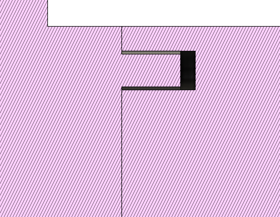
Each registration peg on the base is 0.15-inches in diameter and each hole it goes into has a 0.2mm tolerance in the diameter and a 0.2-inch total depth in the bottom of the hole. What this allows you to do is to use expanding super glue (like Gorilla glue) to fill the tolerance areas around the peg and create a strong bond while putting the pieces together.
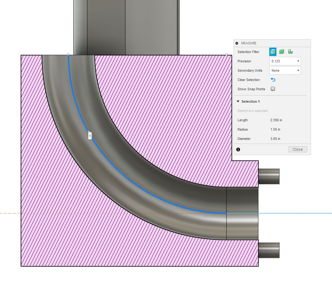
The hole through the leg is a sweep of a 0.5-inch diameter circle along a path. The radius of the bend from side to top is a 1.5-inch radius.
The base vertical piece is attached to the base and begins the overall vertical section. We'll talk about that next...
The Lamp Post
In other words, the vertical section of the AmbiLamp.
The vertical sections have a geometry that allows them to be flat (with a 12mm width) for the LED strip(s) to be attached to them but also allows the light to diffuse. The first version of the AmbiLamp had sharp edges that caused the light to be "cut off" and not really disperse on the wall.
Here's the geometry from the top:
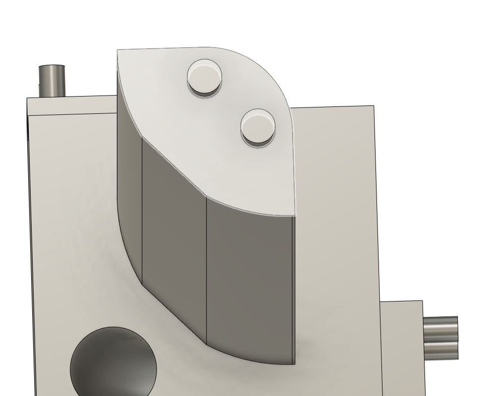
The registration pegs for the vertical section are 0.2-inches in diameter and have been extruded 0.2-inches, and again have a 0.2mm tolerance in the vertical and a 0.25-inch total depth in the registration hole.
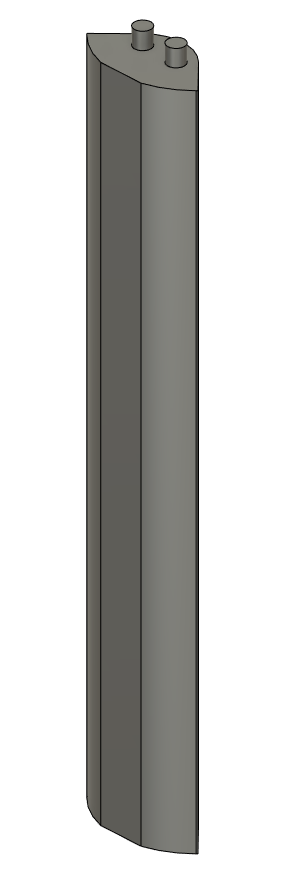
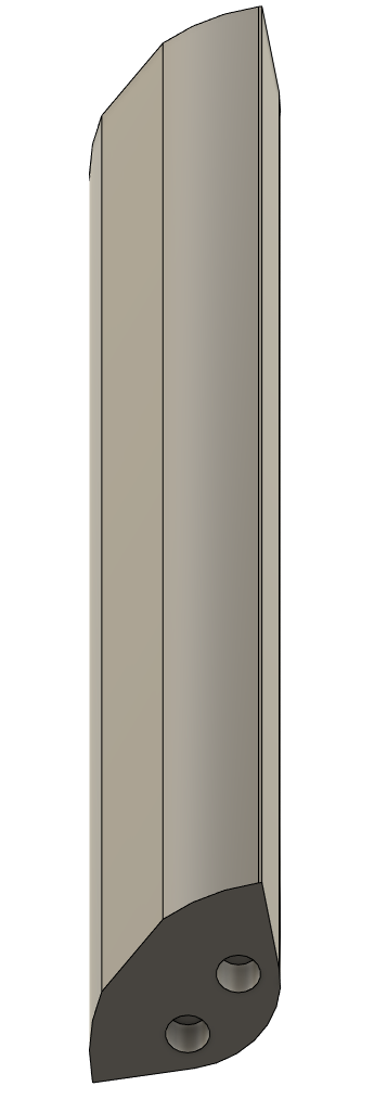
Each "section" of the lamp post has these registration pegs and holes, except for the top vertical piece which only has the registration holes and a flat top. Here are some more photos of the vertical sections from different angles:
Print Settings
I'm going to repeat a bit of what I wrote at the very top of this entry here. I wanted to put the "how to print and assemble" instructions at the beginning for the folks who see this on the internet.
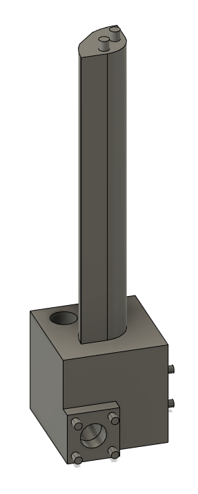
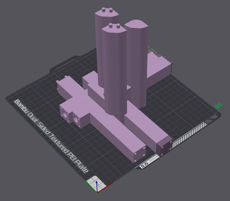
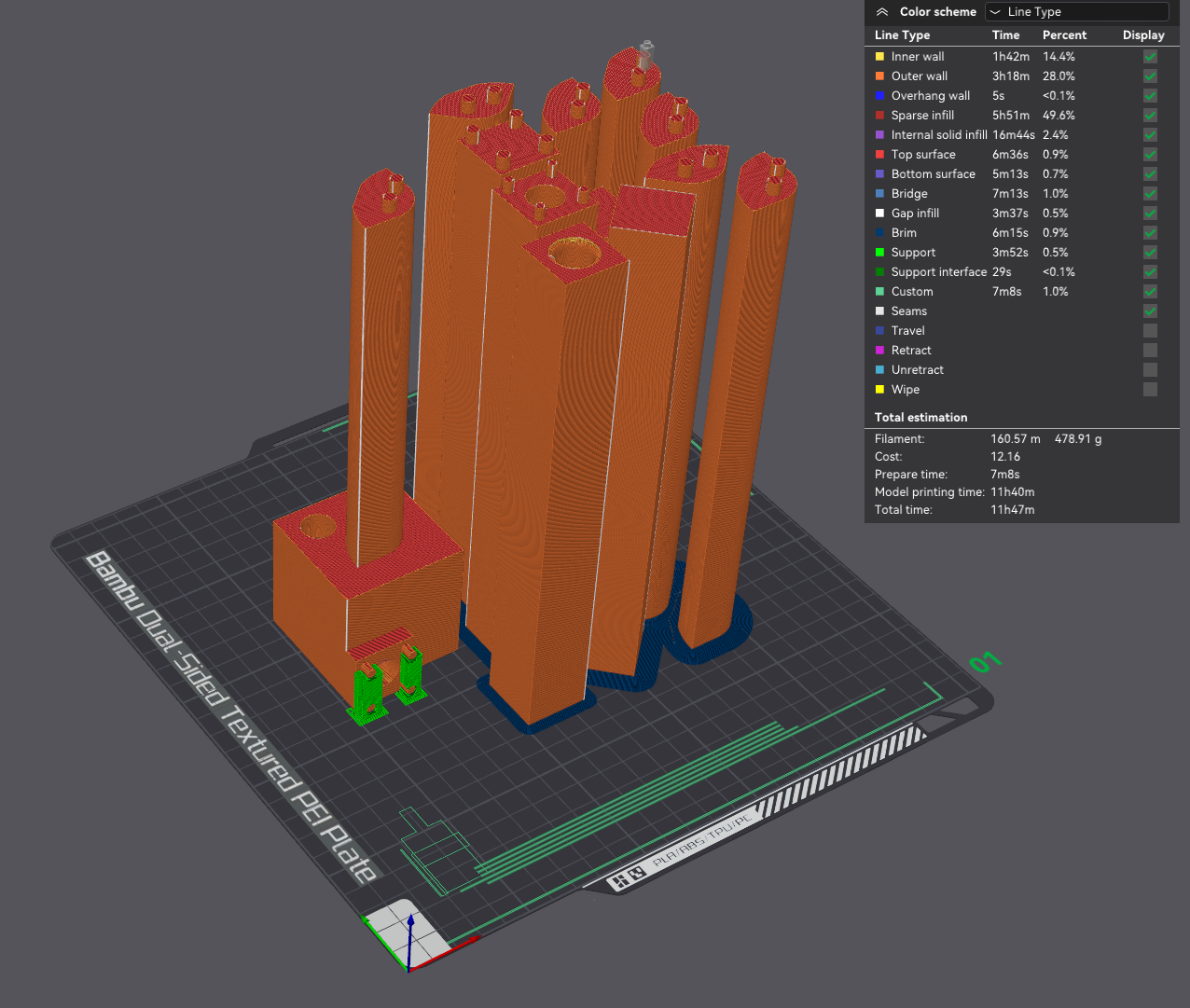
I currently am using a Bambu Lab X1 Carbon printer, and with it's build volume I am able to fit all 12 parts into a single build plate. At first, because of the way each body is exported from Fusion, all the parts are imported looking like this:
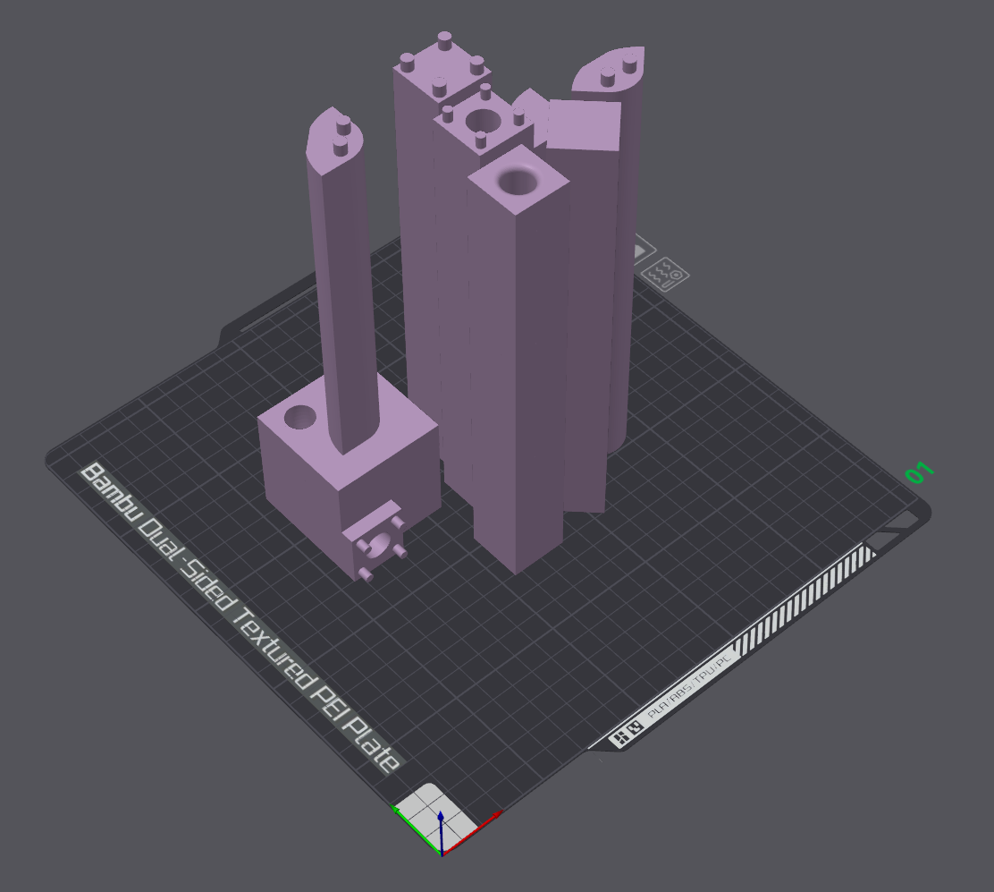
As mentioned in the very beginning, it's best to print these parts with the registration holes on the build plate. With the parts rotated, here's what that looks like:
The image above includes all the necessary parts, except we need to make 5 more copies of the vertical intermediate section. A full build plate looks like this:
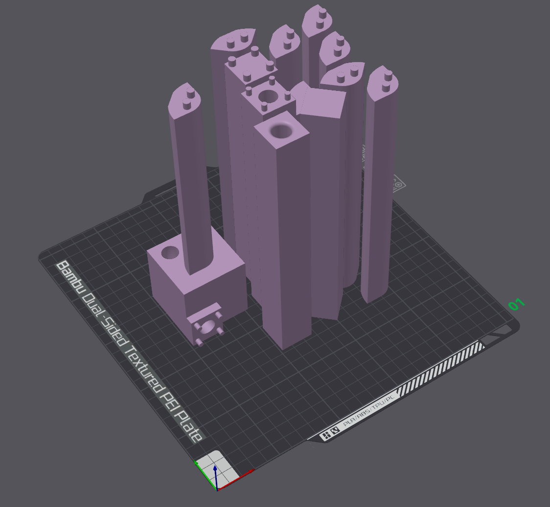
After painting on support for the base's registration pegs, and sliced at the default Bambu profile at 0.2mm layer height, this ends up being a total print time of 11 hours and 40 minutes.
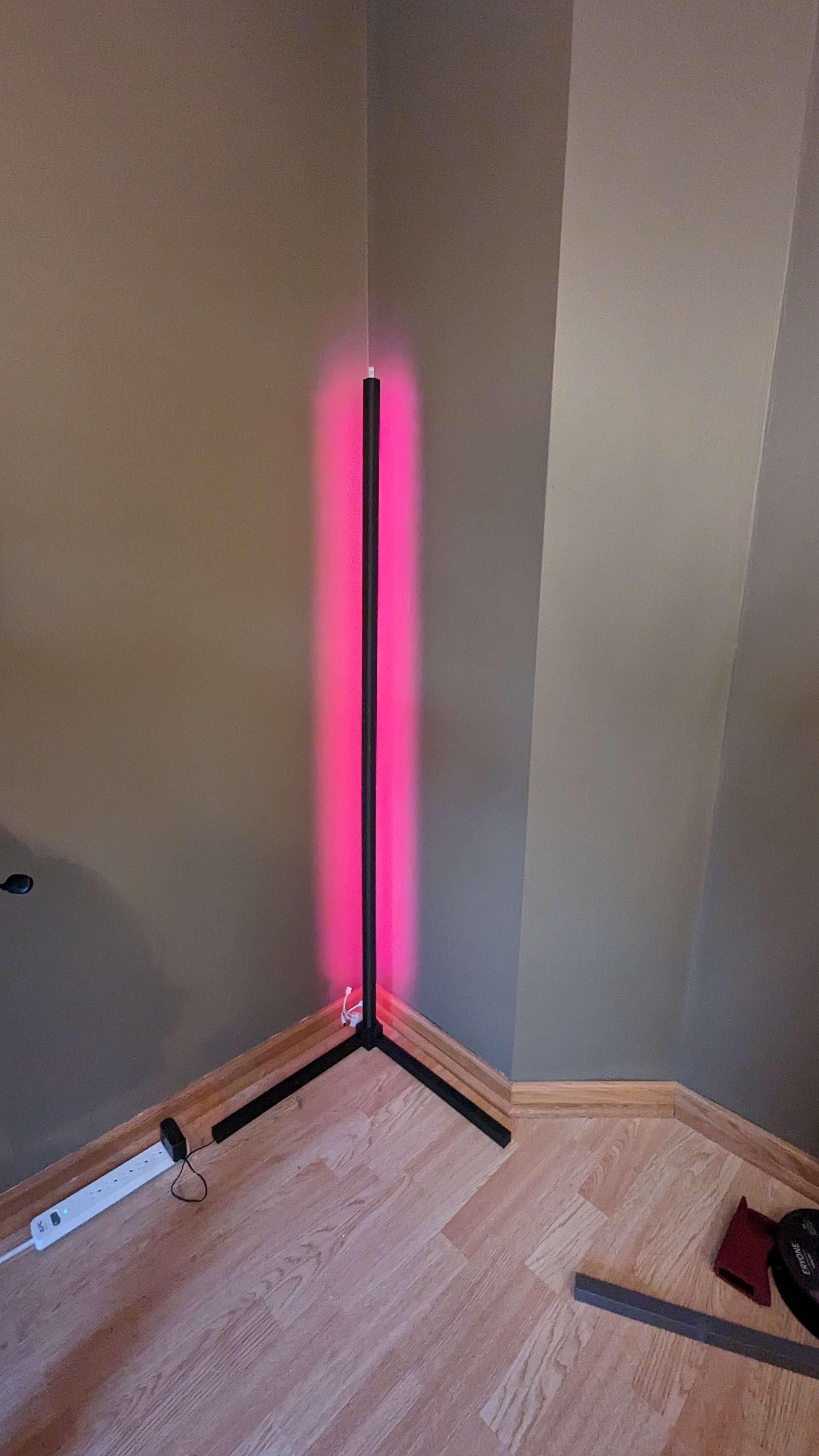
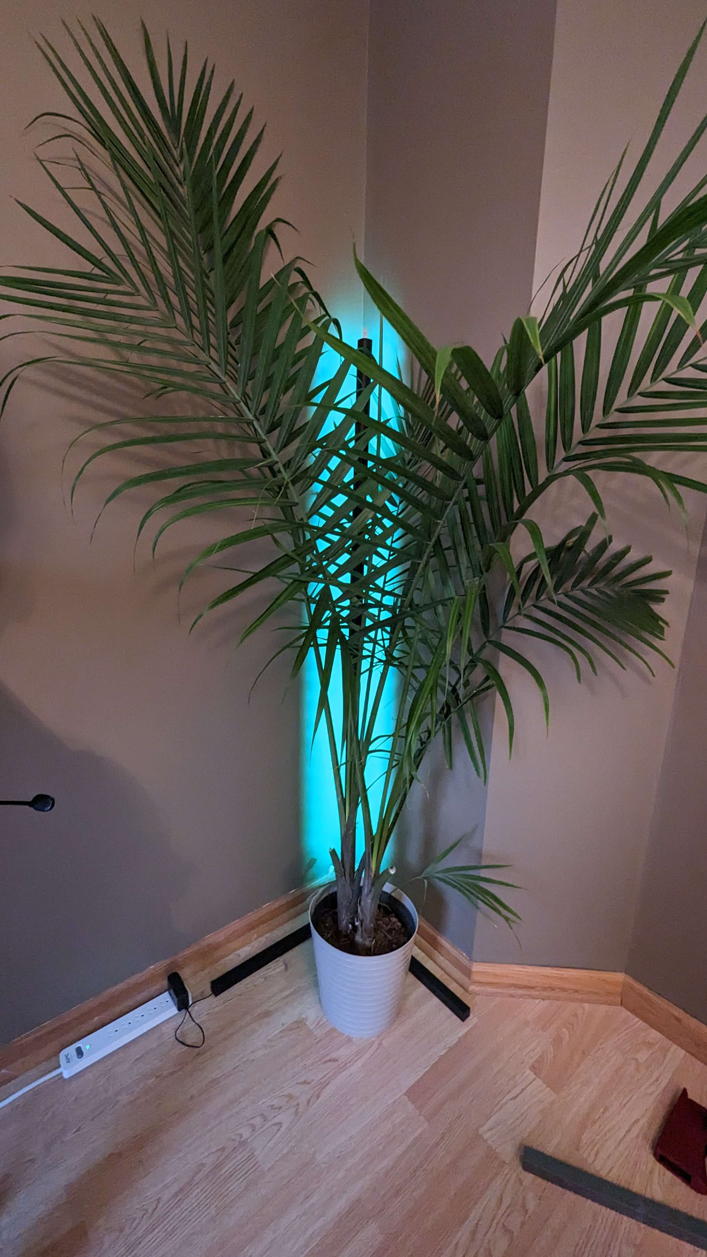
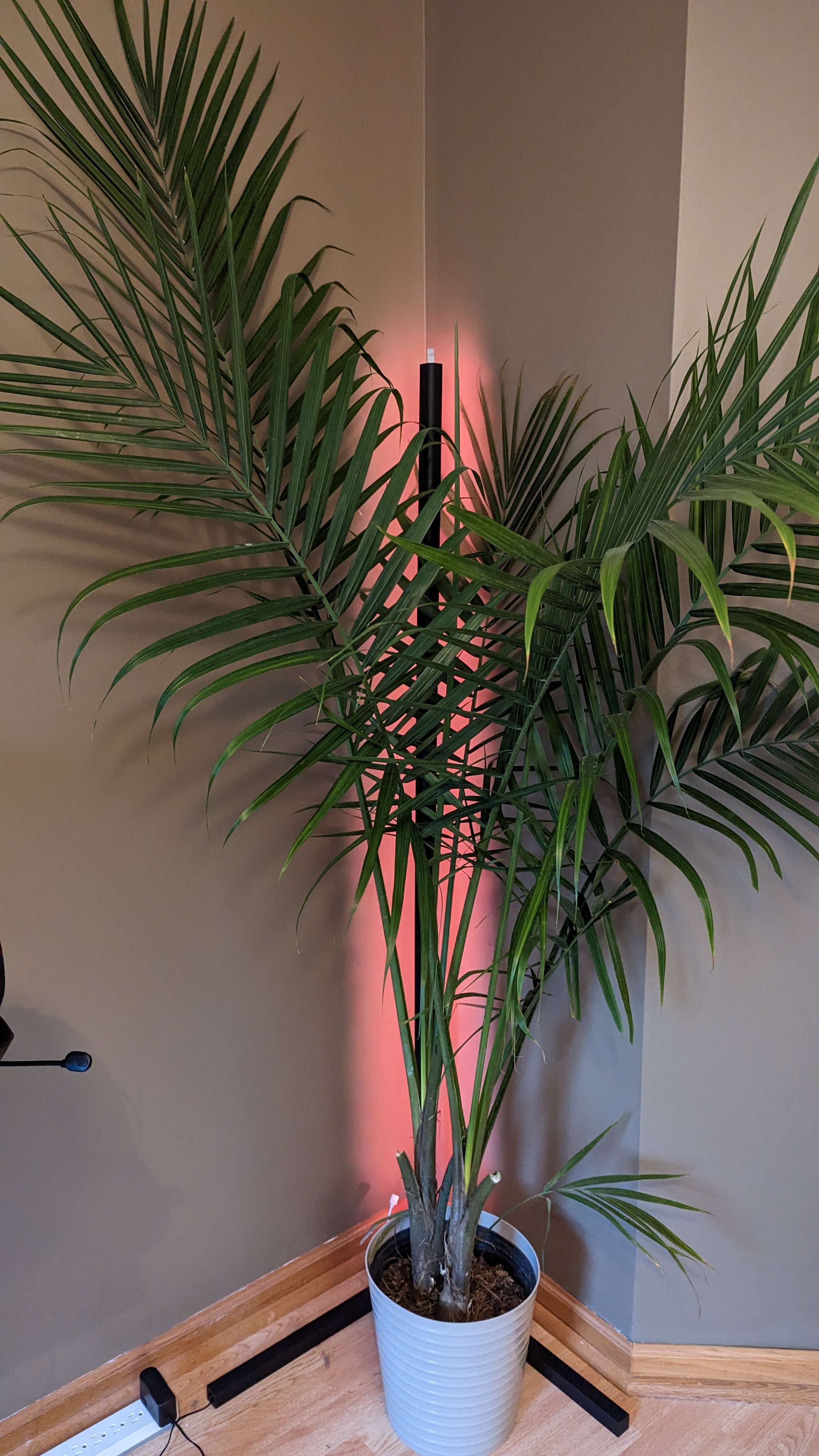
And... that's really it. I printed the pieces over night, assembled in in about 2 hours (glue drying without activator just takes some time), and now it looks like:
Where you can get the models:
Want to donate? Paypal is perfect. Have questions? Shoot me an email or hit me up on mastodon